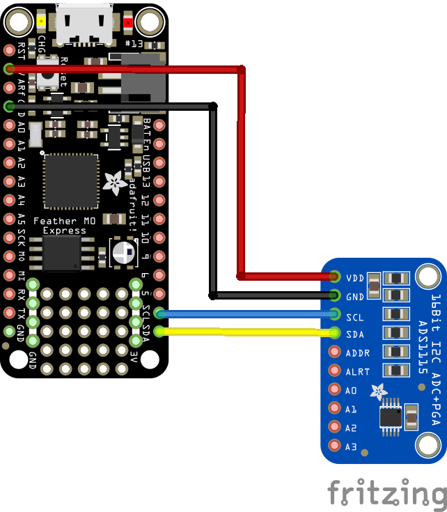
In this example we connect a ADS1115 analog-to-digital converters to an Adafruit Feather M0 running Circuitpython
First lets look at some information about the sensor from the manufacturer
Description
The ADS1113, ADS1114, and ADS1115 devices (ADS111x) are precision, low-power, 16-bit, I2C-compatible, analog-to-digital converters (ADCs) offered in an ultra-small, leadless, X2QFN-10 package, and a VSSOP-10 package. The ADS111x devices incorporate a low-drift voltage reference and an oscillator.
The ADS1114 and ADS1115 also incorporate a programmable gain amplifier (PGA) and a digital comparator. These features, along with a wide operating supply range, make the ADS111x well suited for power- and space-constrained, sensor measurement applications.
The ADS111x perform conversions at data rates up to 860 samples per second (SPS). The PGA offers input ranges from ±256 mV to ±6.144 V, allowing precise large- and small-signal measurements.
The ADS1115 features an input multiplexer (MUX) that allows two differential or four single-ended input measurements. Use the digital comparator in the ADS1114 and ADS1115 for under- and overvoltage detection.
The ADS111x operate in either continuous-conversion mode or single-shot mode. The devices are automatically powered down after one conversion in single-shot mode; therefore, power consumption is significantly reduced during idle periods.
Features
Wide Supply Range: 2.0 V to 5.5 V
Low Current Consumption: 150 µA (Continuous-Conversion Mode)
Programmable Data Rate: 8 SPS to 860 SPS
Single-Cycle Settling
Internal Low-Drift Voltage Reference
Internal Oscillator
I2C Interface: Four Pin-Selectable Addresses
Four Single-Ended or Two Differential Inputs (ADS1115)
Programmable Comparator (ADS1114 and ADS1115)
Operating Temperature Range: –40°C to +125°C
This is the sensor I bought
Parts Required
| Name | Link |
| Adafruit Feather M0 Express | Adafruit (PID 3403) Feather M0 Express – Designed for CircuitPython – ATSAMD21 Cortex M0 |
| ADS1115 | ADS1115 Ultra-Compact 16-Bit Precision Analog-to-Digital Converter |
| Connecting cables | Free shipping Dupont line 120pcs 20cm male to male + male to female and female to female jumper wire |
Schematic/Connection

feather and ADS1115
Code Example
I used Mu for development
The following is based on a library , I copied the adafruit_ads1x15 folder which contains a library for this device to the lib folder on my Feather M0 Express – https://circuitpython.org/libraries
[codesyntax lang=”python”]
import time
import board
import busio
import adafruit_ads1x15.ads1115 as ADS
from adafruit_ads1x15.analog_in import AnalogIn

# Create the I2C bus
i2c = busio.I2C(board.SCL, board.SDA)

# Create the ADC object using the I2C bus
ads = ADS.ADS1115(i2c)
# you can specify an I2C adress instead of the default 0x48
# ads = ADS.ADS1115(i2c, address=0x49)

# Create single-ended input on channel 0
chan0 = AnalogIn(ads, ADS.P0)
chan1 = AnalogIn(ads, ADS.P1)
chan2 = AnalogIn(ads, ADS.P2)
chan3 = AnalogIn(ads, ADS.P3)

# Create differential input between channel 0 and 1
# chan = AnalogIn(ads, ADS.P0, ADS.P1)

print("{:>15}\t{:>2}".format("raw", "v"))

while True:
    print("Channel 0 : {:>5}\t{:>5.3f}".format(chan0.value, chan0.voltage))
    print("Channel 1 : {:>5}\t{:>5.3f}".format(chan1.value, chan1.voltage))
    print("Channel 2 : {:>5}\t{:>5.3f}".format(chan2.value, chan3.voltage))
    print("Channel 3 : {:>5}\t{:>5.3f}".format(chan3.value, chan3.voltage))
    time.sleep(0.5)
[/codesyntax]
Output
Here is what I saw in Mu REPL window
Channel 0 : 4699 0.590
Channel 1 : 4702 0.589
Channel 2 : 4709 0.588
Channel 3 : 4713 0.591
Channel 0 : 4699 0.590
Channel 1 : 4700 0.589
Channel 2 : 4708 0.588
Channel 3 : 4715 0.591
Channel 0 : 4695 0.590
Channel 1 : 4698 0.590
Channel 2 : 4702 0.588
Channel 3 : 4716 0.590
Links
http://www.ti.com/lit/ds/symlink/ads1015.pdf


